Bridges in West Virginia are supported on rock at an average depth of about 19 feet. Based on field review of scour in rock at our existing bridges, the occurrence of rock scour is infrequent and usually shallow in depth. Nonetheless, scour of rock can be, at worst, several feet deep and can endanger the public and reduce the life of a bridge. Based on our review of the scour modes in West Virginia, dislodgment (also known as plucking and quarrying) is the most significant form of scour. Currently, dislodgment scour is estimated empirically due to the complexity of the hydraulics problem. When thinly bedded rock is exposed to high flow velocities, as much as five (5) feet of dislodgment rock scour over the life of the bridge has been observed in West Virginia (see photographs at end).
Rock scour due to abrasion occurs over time with the power of flowing water carrying particles of silt, sand, and gravel that will gradually wear down the rock, grain-by-grain, in the stream bed. Abrasion is more erosive on soft rock such as claystone, soft shale and soft siltstone as well as poorly cemented, coarser grain rock. Based on our visual observations, abrasion is not a concern for harder rock (see photographs). Soft rock should be avoided as support of a foundation element when it is directly exposed to the flowing water. When exposed, softer rock types must support a foundation, abrasion can be analytically estimated by cumulative stream-power and laboratory continuous slake tests (refer to Keaton et. al., 2012, Wait & Neiman et. al., 2013) to determine the minimum embedment depth.
When estimating scour empirically, the geotechnical engineer should look at the site for signs of existing rock scour and to determine if soft or thinly bedded bedrock is exposed in the stream bed. If thinly bedded rock is exposed, then extra caution is needed when locating the footing depth. Similarly, when soft rock is exposed, the footing should be recessed deeper into a more resistive rock layer. Often bedrock is not exposed, and the geotechnical engineer must rely on the core samples or core photographs.
Per LRFD, the minimum embedment of foundations must be presented in the geotechnical report and this requires an assessment of the erodibility of rock and the resulting scour depth. To this end, we offer our guidance as follows:
- 1) Foundation rock is not exposed – review rock core samples or photographs of the core and determine the estimated scour depth as follows:
- If the total scour depth of the stream bed soils does not reach the bedrock surface, then the estimated scour depth of rock is considered to be zero (0); embed the tip or footing a minimum of 1 foot.
- If the total scour prism reaches bedrock, then use one of the following:
- If most of the bedding or discontinuities are less than 2 inches, then embed the tip or footing 5 feet, or to the depth where thicker bedding allows less embedment.
- If the majority of bedding/discontinuities are thicker than 2 inches, but less than 1 foot, then embed a minimum of 2.5 feet.
- If bedding/discontinuities are thicker than 1 foot, then embed a minimum of 1 foot.
- If claystone, soft shale, soft siltstone, or poorly cemented sandstone is present to depths greater than 5 feet, then the continuous slake test, as discussed below, should be used to determine the scour depth over the life of the structure.
- Foundation rock is exposed – visit the site and determine the likelihood of dislodgment or abrasion as follows:
- For design storm velocities less than or equal to 7 fps, use the following:
- Scour countermeasures are effective for abutments and, if used, the estimated scour depth of rock is considered to be zero (0); embed the footing a minimum of 1 foot.
- Scour countermeasures cannot be relied upon at piers and scour must be estimated as discussed under one of the items in section b below.
- For design storm velocities greater than 7 fps at abutments, use the following:
- If most of the bedding or discontinuities are less than 2 inches, embed the tip or footing 5 feet, or to where the bedding allows less embedment.
- If the majority of bedding/discontinuities are thicker than 2 inches, but less than 1 foot, then embed a minimum of 2.5 feet.
- If bedding/discontinuities are thicker than 1 foot, then embed a minimum of 1 foot.
- If claystone, soft shale, soft siltstone, or poorly cemented sandstone is present to depths greater than 5 feet, then the continuous slake test, as discussed below, should be used to determine the scour depth over the life of the structure.
Engineering judgment is needed in conjunction with the above guidance for the final depth of the tip or footing. For example, if a spread footing is used where the scour hole would only expose a small portion of the rock that will not undercut the footing, then it would be judged to be excessive to recess the entire footing one additional foot below the estimated scour depth. Conversely, if much of the front face of the foundation could be eroded, then the engineer may need to recess the entire footing one additional foot for base slide resistance. Of course, a foundation element that requires fixity for lateral loading where erodible rock exists should not include the erodible portion in the fixity depth.
The methodologies for estimating stream power and the continuous slake are outlined in the WVDOH research document entitled Criteria for Predicting Scour of Erodible Rock in West Virginia, RP-273, which is available upon request. The continuous slake durability test can be performed to determine the rock’s Geotechnical Scour Number (GSN) which is a measure of scour versus cumulative stream power. Also, guidance for determining the GSN and cumulative stream power can be found in the National Cooperative Highway Research Program (NCHRP) report 717 (2012) entitled “Scour at Bridge Foundations on Rock”.
The photos that follow show a range of scour in exposed rock observed in West Virginia. Also, photos of core samples with our empirically estimated scour depth are shown to assist the geotechnical engineer.
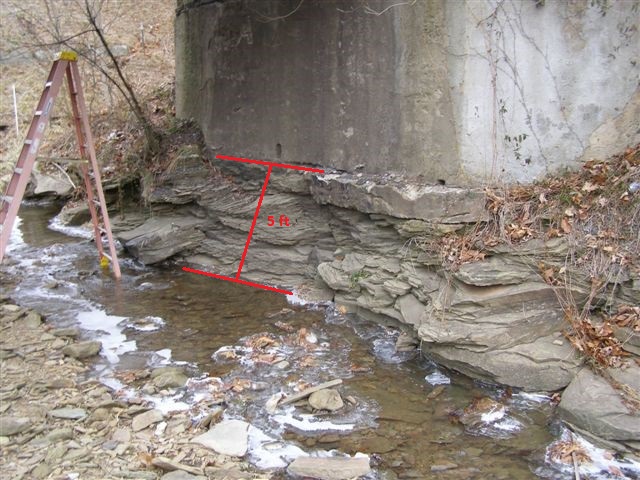
Photograph 1: Five feet of scour in mostly 2” or less bedded rock.
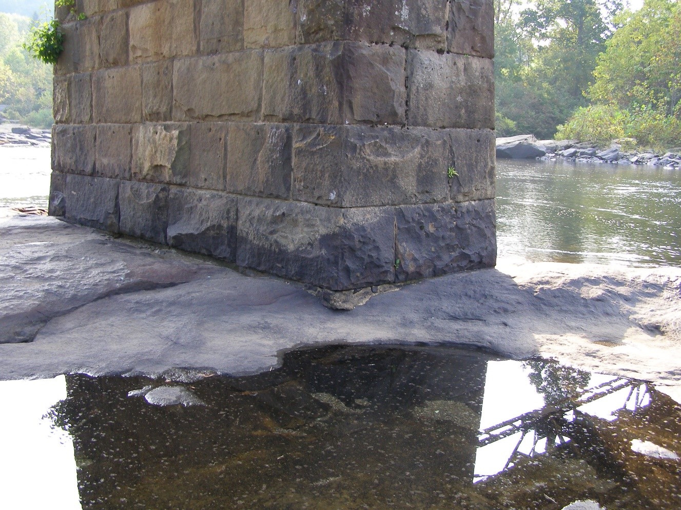
Photograph 2: Minimal abrasive scour of very hard sandstone at a pier over 100 years old.
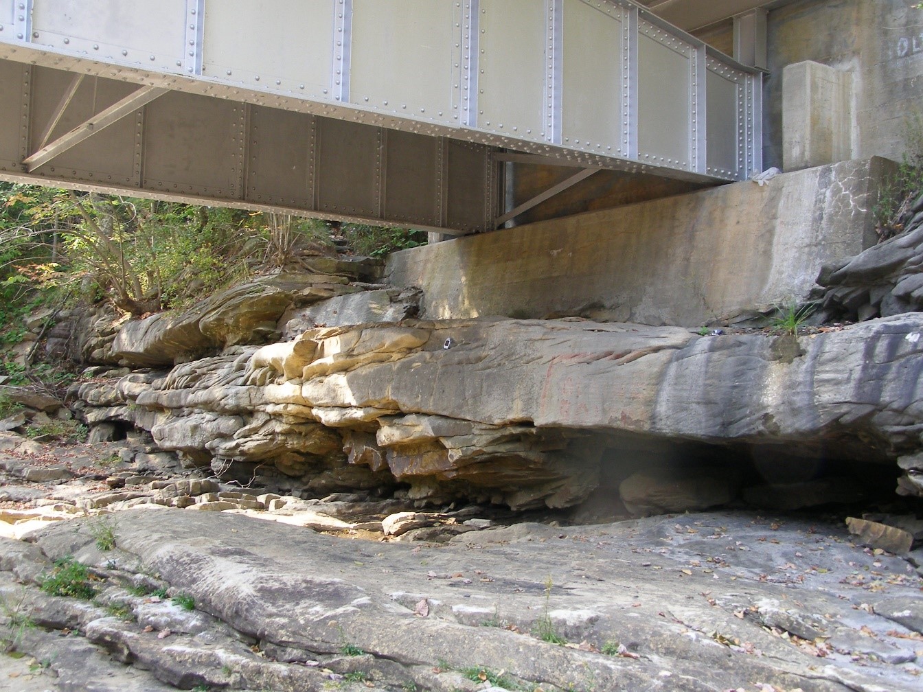
Photograph 3: Thickly bedded sandstone above and below undercut in weakly cemented sandstone.
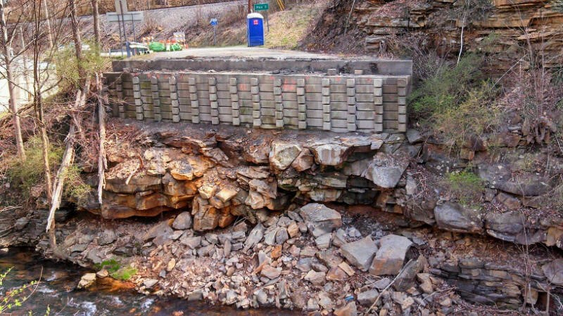
Photograph 4: Broken, thickly bedded sandstone dislodging above undercut.
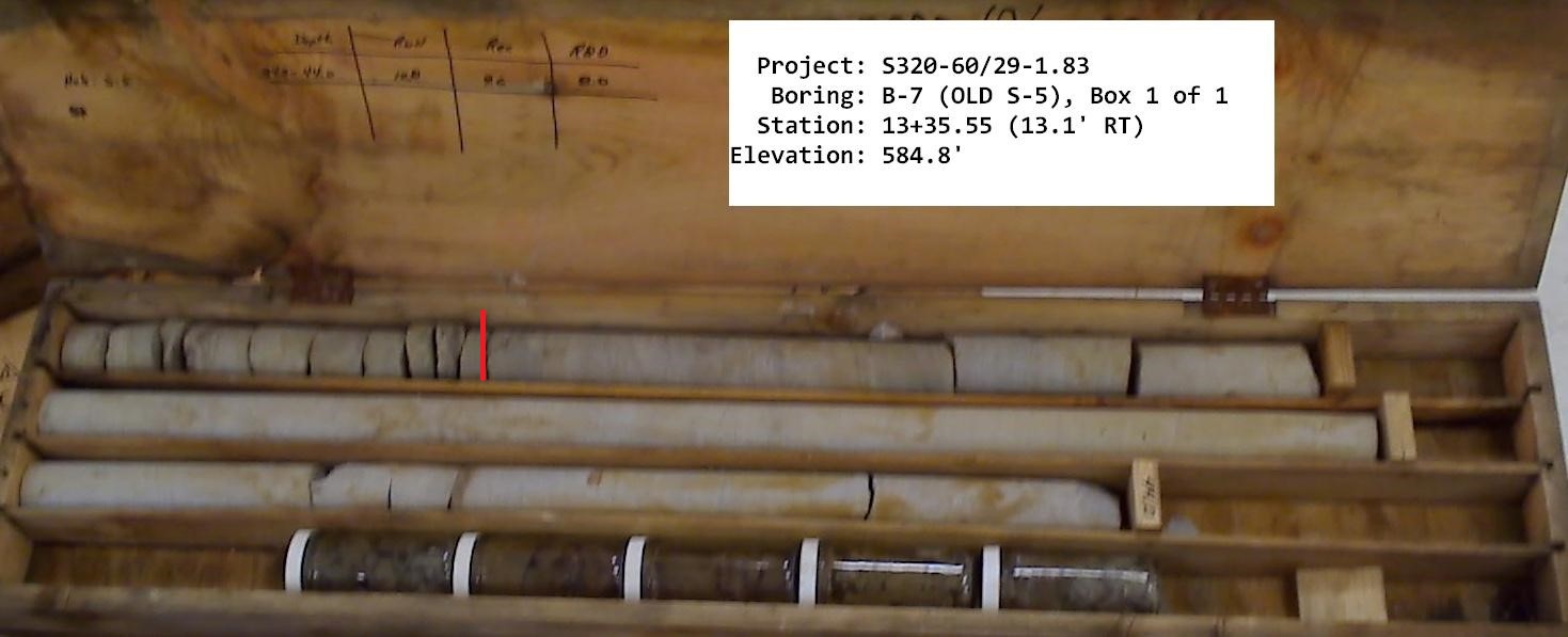
Photograph 5: Example of determining footing depth by reviewing rock core photographs.
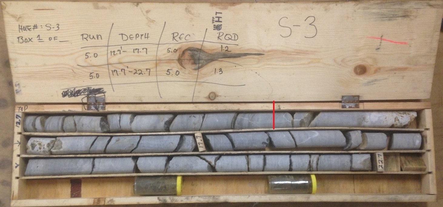
Photograph 6: Example of determining footing depth where discontinuities are mostly between 2 inches and 1 foot. The mark is at about 2.5 feet below the bedrock surface.
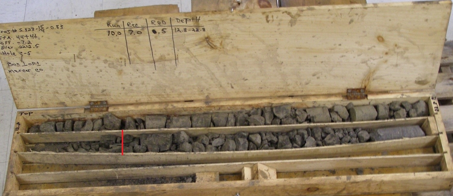
Photograph 7: Example of determining footing depth where most of the pieces are 2 inches or less. The marked depth is about 5 feet deep.
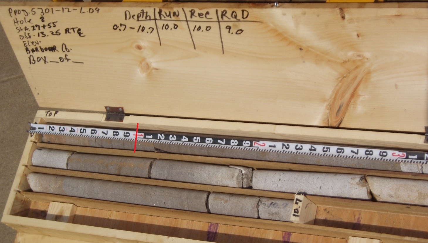
Photograph 8: Example of non-erodible rock; however, we would embed the footing a minimum of 1 foot.